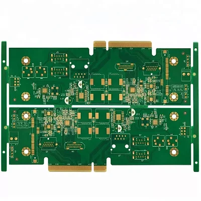
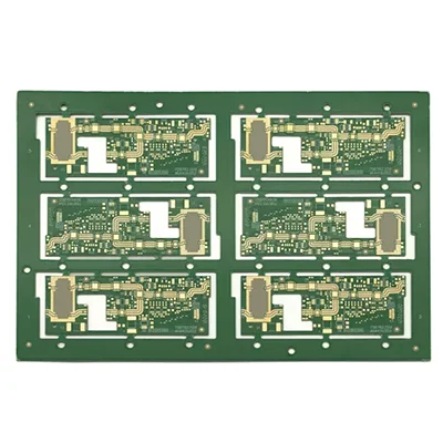
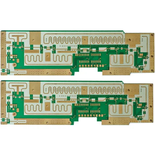
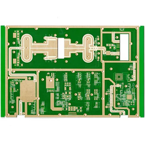
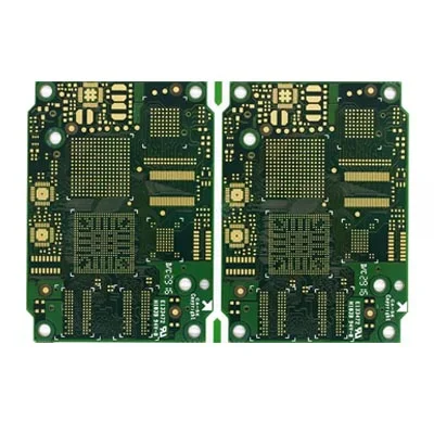
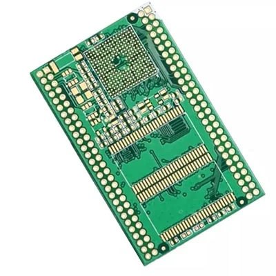
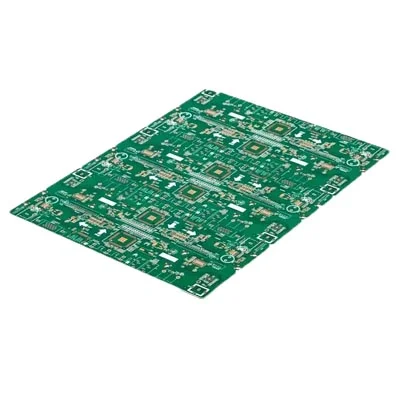
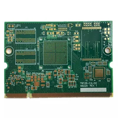
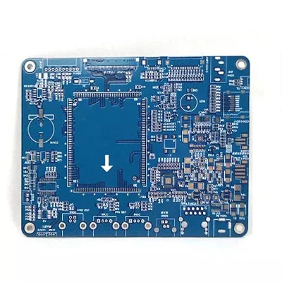
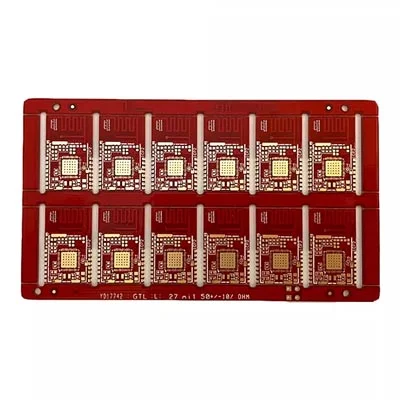
Ten-layer HDI Impedance Controlled Automotive Digital PCB
Send Inquiry
Why does PCB need impedance?
Viafull is one of the professional Ten-layer HDI Impedance Controlled Automotive Digital PCB manufacturer and supplier in China.
1. Check the table line to consider the installation of electronic components and consider the conductivity after insertion. Therefore, the lower the impedance, the better the resistance.
2. PCB circuit boards must go through copper cladding, electroplating tin, connection welding and other process production links. The materials used in these links must ensure low resistivity to ensure that the overall impedance of the circuit board can meet the product quality requirements and ensure the normal operation of the product.
3. Tin plating of PCB circuit boards is the most common problem in the entire circuit board production and is a key link affecting impedance. The biggest defect of the chemical tin plating layer is that it is easy to change, and the tin is poor, which will cause the circuit board to be difficult to solder. Excessive impedance leads to poor conductivity or unstable rectification performance.
4. There will be various signal transmissions in the conductors in the PCB circuit board. When the transmission rate increases, the frequency must increase. If the line itself is different due to corrosion, stacking thickness, line width, etc., it will cause changes in the impedance value. Its signal is distorted, resulting in a decrease in the performance of the circuit board, so the control value needs to be controlled within a certain range.
Data Sheet
| Name: | 10-layer HDI impedance-controlled automotive digital PCB |
| Base material: | FR-4 |
| Copper thickness: | 1 ounce |
| Board thickness: | 1. 6MM |
| Surface treatment: | 45% immersion gold |
| Circuit board size: | 90. 10*102. 11MM/2PCS |
| Material: | FR-4 |
| Board thickness: | 1. 6MM |
| Number of layers: | 10L1/H/H/H/H/H/H/H/H/1OZ |
| Single chip size: | 49. 93*70. 07MM |
| Connection size: | 90. 10*102. 11MM/2PCS |


