

Products


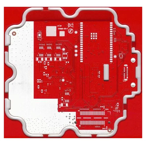
Rogers RO4835 77G Millimeter Wave Radar Board
The producers of Viafull in China offer high-quality products, you are welcome to purchase straight high-quality Rogers RO4835 77G Millimeter Wave Radar Board at a good price.
Send Inquiry
Product Description
Millimeter-wave radar mainly uses 24G radar PCB and 77G radar PCB. Millimeter-wave radar PCB is mainly used for automotive AI intelligent unmanned driving.
Millimeter-wave radar PCB has broad application prospects. At present, PCB uses Rogers RO3003G2+ITEQ IT180 to mass-produce 77GHz millimeter-wave radar PCB.
A common feature of different radar PCB designs of millimeter-wave radar sensors is the need for ultra-low loss radar PCB materials to reduce circuit loss and increase antenna radiation. Radar PCB materials are key components in radar sensor design. Choosing suitable radar PCB materials can ensure the stability and consistency of millimeter-wave radar sensors.
How to design the performance of radar PCB:
First of all, the electrical properties of radar PCB materials are the primary factors in designing radar sensors and selecting radar PCB materials. Choosing radar PCB materials with stable dielectric constants and ultra-low losses is crucial to the performance of 77GHz millimeter-wave radars. Stable dielectric constants and losses can enable the antenna to receive and receive accurate phases, which can improve the antenna gain, scanning angle or distance, and improve the accuracy of radar detection and positioning. The stability of the dielectric constant and loss characteristics of the PCB not only ensures the stability of different batches of materials, but also ensures small variation and good stability within the same PCB board.
Data Sheet
| Product name: | Rogers RO4835 77G millimeter wave radar board |
| Board: | Rogers RO4835+FR4 |
| Dielectric constant: | High frequency material dielectric constant 3. 48 |
| Dielectric thickness: | 4mil (0. 1mm) |
| Number of layers: | 6 layers |
| Board thickness: | 1. 2mm |
| Copper thickness: | 1oz for inner and outer layers |
| Via: | Resin plug |
| Surface process: | Chemical gold immersion |
| Thermal conductivity: | 0. 69w/m. k |
| Loss: | 0. 003 |
Hot Tags: Rogers RO4835 77G Millimeter Wave Radar Board
Send Inquiry
Please feel free to fill your inquiry in the form below. We will reply you in 24 hours.


X
We use cookies to offer you a better browsing experience, analyze site traffic and personalize content. By using this site, you agree to our use of cookies.
Privacy Policy